Tag Archives: Azure Iaas

#Azure: Azure Import/Export service


Azure Import/Export service allows data transfer between Azure datacenters and customer locations. It is a secure service to send or receive medium-to-large amount of data when the bandwidth becomes bottleneck and costly. Azcopy is preferred tool for online data migration if you look Microsoft Azure data transfer options. While Azure Import/Export provides large amount of physical data transfer in secure and reliable manner. The data can be copied in one or more drives to import to and to export from Azure blob and file storages.

This Import/Export service use either 2.5-inch SSDs or 2.5/3.5-inch SATA II & III HDDs or mix of these. External HDD with built-in USB adapter and drives in external casing are not supported. Here is the quick snapshot of possible import and export data transfers.

Job Storage Accounts Supported Not Supported
Import Classic

Blob Storage accounts

General Purpose v1 storage accounts.

Azure Blob storage.

Block/page blobs.

Azure File storage.

Export Classic

Blob Storage accounts

General Purpose v1 storage accounts.

Azure Blob storage.

Block, page and append blobs.

Azure File storage.

Points to remember while sending drives for import job.

  • A maximum of 10 drives for each job.
  • Use only single data volume partition.
  • Data volume must be formatted with NTFS.
  • Supported external USB adaptors to copy data to internal HDDs.
    • Anker 68UPSATAA-02BU
    • Anker 68UPSHHDS-BU
    • Startech SATADOCK22UE
    • Orico 6628SUS3-C-BK (6628 Series)
    • Thermaltake BlacX Hot-Swap SATA External Hard Drive Docking Station (USB 2.0 & eSATA)

Let me explain you use cases and process to perform import/export job.

You can use this service in following scenarios:

  • Move data to the cloud as part of the data migration strategy.
  • Data backup to the cloud.
  • Data recovery from the cloud.
  • Data distribution to the customer sites.

Here is the high-level process and components and locations available for Import/Export job.

Components:

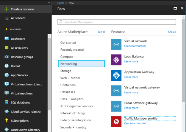
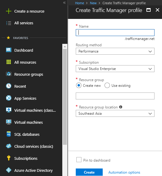
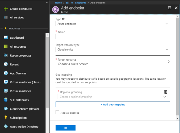
  • Import/Export service in Azure portal to create a new job
  • Hard disk drives to copy the data
  • WAImportExport tool to prepare drives and encrypt data

Location available on the date of writing this blog post:

Country Country Country Country
East US North Europe Central India US Gov Iowa
West US West Europe South India US DoD East
East US 2 East Asia West India US DoD Central
West US 2 Southeast Asia Canada Central China East
Central US Australia East Canada East China North
North Central US Australia Southeast Brazil South UK South
South Central US Japan West Korea Central Germany Central
West Central US Japan East US Gov Virginia Germany Northeast

Courtesy: Microsoft

If your Azure storage account location is not available in the above list, you can create a job and send it to the alternate location as specified in the tool while creating an Import job.

Next blogpost covers, step by step process of Azure Import/Export service/job.

#Azure : Traffic Manager


Azure traffic manager is nothing but it is your global DNS load balancer that help you to manage the traffic across multiple datacenter and regions. Traffic manager uses the DNS to direct client requests to the multiple endpoints in most appropriate way. With the help of traffic manager, clients connect directly to the endpoints. Traffic manager can also be leveraged for external, non-Azure endpoints.

Let me show, how to create and configure traffic manager step-by-step.

Login to the Azure Portal and select “+ Create a resource”. Select the “Networking” and then select “Traffic Manager”.

Here you define the name of the traffic manager, routing method, subscription, resource group and location.

Name: you should use unique prefix for your traffic manager profile. For Example, if I use ex-tm as a prefix for my traffic manger profile that will be associated with my global Exchange deployment then complete name of this traffic manager profile would be ex-tm.trafficmanager.net. Make sure this name can’t be changed once created.

Define the routing method that you wish to use for your traffic manager profile. However, you can change your routing method from configuration panel as well.

Once defined all the necessary details, click on “Create” to setup a traffic manager profile.

Once traffic manager profile created, you can see the basic configuration from overview panel.

Go to the Configuration panel under settings to configure your traffic manager profile.

Routing Method: Select routing method based on your need. Azure traffic manager profile provides four different types of routing methodologies.

Priority: Use this routing method when you want to route all the traffic to a primary service endpoint, and based on the configuration, traffic can be routed to backup service endpoints if primary service endpoint fails. In simple words, it is kind of active passive routing methodology.

Weighted: Weighted routing methodology can be leveraged when you want to distribute traffic based on the weight assigned to the specific set of endpoints or multiple set of endpoints based on the weight.

Performance: Performance routing methodology is beneficial when you want to distribute traffic according to performance. Here performance criteria is network latency, therefore the traffic will be redirected based on the lowest network latency. It could be the closest location and in some it will not be the closest location as well.

Geographic: Geographic routing as name suggests, it is based on the location from where the DNS query originates. It helps in redirecting requests to the based on the geographic region to improve user experience, to comply with data regulations etc.

DNS time to live (TTL): As it is based on DNS query, therefore you need to define a response time of the query. By default, it is set to 300 sec.

Endpoint monitor settings:

  • Protocol: Select protocol for endpoint probing to check the health of the service endpoints. You get three protocol, HTTP, HTTPS, and TCP. In case of HTTPS, probe only check the availability of certificate but doesn’t check the validity of certificate.
  • Port: Select the port number based on protocol.
  • Path: Define the path setting for HTTP and HTTPS protocol. Use relative path and name of the webpage name for TCP, forward slash (/) is a valid entry for the relative path.

Fast endpoint failover settings:

  • Probing interval: Enter the interval time for probing to check the health of the service endpoint. You can choose between 10 seconds for fast probing and 30 seconds for normal probing.
  • Tolerated number of failures: you can the define number of probing failures between 0 to 9.
  • Probe timeout: Probe timeout should be minimum 5 seconds and maximum should be less than the probing interval.

Generate key from Real user measurements panel under settings. Any measurement, you send and receive any traffic from an application to traffic manager is identified by the RUM Key. To know more about it in detail and how to embed it within the application, click here.

From the Traffic view panel under settings, you can enable the traffic view to view location, volume and latency information for the connections between your users and Traffic Manager endpoints.

From Endpoints panel under settings, add all your service endpoints.

Azure traffic manager supports three types of endpoints.

  • Azure endpoints: Use this type of endpoint to load-balance the traffic of Azure cloud services.
  • External endpoints: Use this type of endpoints if you want to load-balance external services, which are outside the Azure environment.
  • Nested endpoints: Nested endpoints are little advance level configuration in which child traffic manager profile check the health probes and propagate the results to parent traffic manager profile to decide the service endpoints.

Based on the endpoint type selection, fill rest of the required details and then add the endpoints.

In the properties section, you can look at the traffic manager profile properties.

Under the locks section, you can create and configure the lock type to prevent changes and protecting the azure traffic manager profile.

Under the “Automation script” download the script or add to library for reuse.

In the metrics panel, you can monitor the metrics of traffic manager profile by two different parameters:

  • Endpoint Status by Endpoint
  • Queries by Endpoint Returned

I hope, this article helped you to understand, create, configure and manage Azure traffic manager.

#Azure : Application Gateway


Like your layer 7 load balancer in your traditional datacenter, Azure application gateway takes care of your HTTP/HTTPS based requests. It works at application layer (level 7 of OSI model) and works as a reverse-proxy as well. In application gateway, client connections are terminated at gateway and then forwarded to application.

Let me show, how to create and configure application gateway step-by-step.

Login to the Azure Portal and select “+ Create a resource”. Select the “Networking” and then select “Application Gateway”.

In the basic configuration settings:

Enter the name of the application gateway. Always use a name for any components in Azure that fit for purpose and easy to distinguish.

Select the application gateway tier:

  • Standard: As any other layer 7 load balancer, it provides HTTP(S) load balancing, cookie-based session affinity, secure sockets layer (SSL) offload, end-to-end SSL, URL based content routing, multi-site routing, websocket support, health monitoring, SSL policy and ciphers, request redirect, and multi-tenant back-end support etc.
  • WAF: WAF is an advanced version of standard application gateway with application firewall capabilities that supports all standard AG features along with protection of web applications from common web vulnerabilities and exploits. Application gateway WAF comes pre-configured with OWASP (online web application security project) modsecurity core rule set (3.0 or 2.29) that provides baseline security against many of these vulnerabilities. It provides protection against SQL injection, cross site scripting, command injection, HTTP request smuggling, HTTP response splitting, remote file inclusion attack, HTTP protocol violations and anomalies, bots, crawlers, scanners, application misconfiguration and HTTP Denial of Service etc.

Select SKU size based on your requirement. AG sku comes in small, medium and large size.

Select instance count based on your need. The default instant count is 2.

Select subscription, resource group and location.

Once completed all basic configuration settings, click on OK.

In settings panel, complete following application gateway specific configuration settings:

Select virtual network and subnet that is going to associate with this application gateway.

Complete frontend IP configuration based on your application gateway requirements.

Set idle timeout settings and set the DNS name label.

Select the listener configuration protocol and associated port number.

Once completed with the configuration details, click on OK.

If you select HTTPS in listener configuration, upload PFX certificate file and provide credentials. Once completed with the configuration, click on OK.

Review the summary of the configuration and click on OK to create application gateway.

In the overview section, review the basic configuration.

In configuration panel under settings, you can change the application gateway tier, SKU size and instant count based on your requirements.

In Web application firewall panel under settings, you can upgrade to WAF tier if using standard tier and can also “enable/disable” firewall, configure firewall mode “detection/prevention”, configure rule set with OWASP and advanced configuration for your application gateway.

In Backend pools panel under settings, add and configure backend pools for application gateway. Click on add or existing backend pool to define the backend pool settings.

Click on “+ Add target” to define targets either using “IP address or FQDN” or “Virtual machine”. Click on rules to configure redirection if required.

In HTTP settings under settings, add or edit backend HTTP(S) settings such as cookie based affinity, request timeout, protocol and port etc.

In frontend IP configurations panel under settings, review IP configurations, type, status and associated listeners.

In listeners panel under settings, add basic and multi-site listeners.

In rules panel under settings, define basic and path-based rules based on your requirements.

In health probes panel under settings, you can add and edit health probes.

Once you add health probe, you define following parameters:

Name of the health probe.

Protocol either HTTP or HTTPS.

Enter the host name, path, interval in seconds, timeout in seconds and number of unhealthy thresholds.

In the properties section, you can look at the application gateway properties.

Under the locks section, you can create and configure the lock type to prevent changes and protecting the application gateway profile.

Under the “Automation script” download the script or add to library for reuse.

In the metrics panel, you can monitor the metrics of the application gateway by following parameters:

  • Current Connections
  • Failed Requests
  • Healthy Host Count
  • Response Status
  • Throughput
  • Total Requests
  • Unhealthy Host Count

In alert rules panel under settings, you can define conditional rules.

In diagnostics logs panel under settings, you can view the logs of the resources.

In backend health under settings, you can review the status of the backend pool.

I hope, this article helped you to understand, create, configure and manage Azure application gateways.

#Azure : VNet-to-VNet Connectivity


VNet-to-VNet connectivity is another option to connect two virtual networks. When peering was not available in Azure, VNet-to-VNet connection was the only option to connect two virtual networks either in same region or in two different regions. Connecting a virtual network to another virtual network (VNet-to-VNet) is like connecting a VNet to an on-premises site location. Both connectivity types use an Azure VPN gateway to provide a secure tunnel using IPsec/IKE.

The VNets you connect can be:

  • In the same or different regions
  • In the same or different subscriptions
  • In the same or different deployment models

Let me explain you, how to set it up step by step. Login to the Azure Portal and go to the virtual network.

As you are going to setup a VNet-to-VNet connectivity between two virtual networks, therefore a Gateway subnet and a Network gateway is required in both virtual networks.

Select subnet under settings in virtual network, select “+ Gateway subnet” to create a gateway subnet for this virtual network.

Select an address range that will be used by this network gateway. By default, it selects next available address range.

In my case, I am using last subnet of my address space for gateway subnet.

Once added, you can review all used subnets in subnet panel.

Once, you have setup the subnet gateway in your virtual network then move on and create virtual network gateway to attach with gateway subnet.

Define the name of the virtual network gateway. Select the gateway type to “VPN” as we are establishing VNet-to-VNet connection. Select VPN type either Route-based or Policy-based according to your requirements. Select the VPN SKU based on your need.

Gateway SKUs by tunnel, connection, and throughput:

SKU S2S/VNet-to-VNet
Tunnels
P2S
Connections
Aggregate
Throughput Benchmark
VpnGw1 Max. 30 Max. 128 650 Mbps
VpnGw2 Max. 30 Max. 128 1 Gbps
VpnGw3 Max. 30 Max. 128 1.25 Gbps
Basic Max. 10 Max. 128 100 Mbps

Courtesy: Microsoft

Select the resource group, location and subscription etc.

Select your virtual network for which you are setting up this virtual network gateway.

Create new public IP address for your virtual network gateway.

Create public IP address using either Basic SKU or Standard SKU.

Once you are done with all the details, click on “Create” to deploy virtual network gateway.

Follow the same steps for another virtual network as well.

Once completed above steps in both the virtual networks now this is a time to establish a connection between both virtual network gateways which belongs to their respective virtual networks so that both the virtual networks can talk to each other. To do this, go to the “+ Create a resource” and search for “connection”.

Select the “Connection”.

Click on “Create” to establish a connection between virtual networks.

In basic settings select the type of the connection to VNet-to-VNet. Select the appropriate subscription, resource group and location.

Once configured all the basic settings, select “OK”.

Select both the virtual network gateways that needs to be connected, select the checkbox “Establish bidirectional connectivity” if you want to establish two-way connection. Define first and second connection names and then shared key to establish a secure connection.

Select first virtual network gateway.

Select second virtual network gateway.

Define both first and second connection name and enter the shared key, select OK.

Review the details in summary page and select OK to create a connection between virtual network gateways.

Once completed successfully, resources can talk to each other across virtual networks.

#Azure : Network Peering


In Microsoft Azure Virtual Networks, Peering connects multiple virtual networks. It simplifies the connectivity and configuration between virtual networks. Once connectivity established through peering, traffic flows seamlessly between two virtual networks. Traffic between peered virtual network leverages Microsoft infrastructure backbone, much likely traffic is flowing within the same virtual network. However, it doesn’t cover all the scenarios and it is the option available only for virtual networks available in same region. Apart from this major constraint, there are many other restrictions applies to it such as address ranges can’t be added or deleted from the address space of a virtual network once peered with another virtual network. However, peering virtual networks between region is currently in preview for few regions and it may be generally available soon.

Address spaces within same virtual network doesn’t require peering. For example, if I have two address spaces one for corporate network and another for perimeter network, and both are part of the same virtual network then there is no need to establish any kind of connectivity because both networks can talk to each other by default.

Now, let me show you how to setup peering between virtual network.

Login to the Azure Portal and first go to your virtual network and then go to the “Peering” under settings. Select “+ Add” to establish a peering between virtual networks.

In Add peering panel, fill the required details.

Name: Enter a common name for the peering that you can recognized.

Peer details: Select virtual network deployment model.

Subscription: Select the subscription.

Virtual network: Select the destination virtual network.

Configuration: By default, “Allow virtual network access” enabled. If you don’t have specific configuration, go with default configuration.

Once entered all the necessary details then click “OK” to setup a peering.

Once created successfully, you will be able to see it in peering panel.

Follow the same steps in another virtual network as well. Once completed from both the side, you will be able to flow data between peered networks.

#Azure : Virtual Networks


Azure virtual network enables Azure resources to communicate with each other in Azure network and with external resources through internet. Azure virtual network is like your traditional local area network in datacenter. Azure virtual networks can be connected with another virtual network in Azure and with your On-premises datacenter as well. Azure virtual network supports private ip addressing and subnetting as you do in your on-premises network. Azure virtual network supports subnets within a virtual network, the number of subnets can be defined based on the virtual network class and size of each subnets, and it is as same as VLAN in your traditional network. By default, subnets within virtual network can talk to each other without establishing any connection. Once a virtual network created, multiple address spaces can be added based on your need. While doing this entire exercise, please make sure that any ip address or ip addresses range is not overlapping with each other neither across your Azure virtual networks nor with on-premises network.

Let me show you, how to set up virtual networks step by step. To start login to Azure portal.

In Azure portal, select “+ Create a resource” à“Networking” à “Virtual network”.

Look at the details required to create a virtual network.

Name: Name of the virtual network, it should be unique in your Azure environment.

Address space: Define address space based on your requirement.

Subscription: Select your subscription.

Resource: Either create a new one or use existing resource group.

Location: Select location to create this virtual network resource, It will selected automatically if you are using existing resource group.

Subnet: Define the name of the subnet.

Address range: Define the address range for this subnet.

Service endpoints: Define the service endpoints, by default it is disable.

Look at the below screenshots for filled details. Once filled all the required details, click on “Create” to deploy a virtual network.


Once deployed successfully, you can find this virtual network in your resources.


Select “Subnets” to look at/verify your existing subnet. Click on “+ Subnet” to create a new subnet in your existing virtual network.


Enter the name of the subnet and then enter the address range for this subnet. As we had used 172.26.0.0/20 (172.26.0.0 – 172.26.15.255), therefore the next range will start from 172.26.16.0, You can specify the new range based on your need.


Once filled the required details, select “OK” to deploy a new subnet in your existing virtual network.


Once deployed successfully, you can see both your subnets here.


Go to the Address space, if you would like to add a new address space in your virtual network.


Add the address space based on your requirement. (Example: Many organization uses different – different set of ip address ranges for different types of networks. Very simple example is Corporate and Perimeter network.) Once entered the range, click on “Save”.


Once added the address space successfully, define the subnet in that address space.


In connected device panel, you can see the devices that are using ip address from this virtual network.


In subnet panel, you can define multiple subnets based on your define address ranges.


In DNS panel, you can define the custom DNS server addresses based your network design. By default, it uses Azure-provided DNS server.


In peering panel, you can define peering between two virtual networks that belongs to the same region.


In Service endpoints panel, you can specify services endpoints based on your requirement. In general, you don’t have to define any thing here.


In properties panel, you can see the properties of your virtual network, such as resource id, location, resource group etc.


In Locks, you panel you can define the locks for your resources by defining lock type either “delete” or “read-only”.


In the Automation script panel, you can view the temple of this deployment and you also get an option for download, add to library and deploy.


In the diagram panel, you get the graphical representation of all the subnets and associated resources.


I hope, this step by step blog post helped you to create your virtual network and subnets in Microsoft Azure. To know more about the networking features such as Gateway subnet, peering etc., read the next blog post.

#Azure : Storage replication


Microsoft Azure storage offers numerous type of availability and durability of the data, within the datacenter, across datacenters, within the same region, or across regions. Based on your needs, you can select the right replication methodology. For example, if you would like to save your data from catastrophic failure in a single region then choose replication option that supports replication across regions.

Please keep in mind that you can configure replication options when you are creating a storage account and each region doesn’t support all replication options. Microsoft Azure offers four different replication options.

LRS: Locally redundant storage

ZRS: Zone-redundant storage

GRS: Geo-redundant storage

RA-GRS: Read-access geo-redundant storage

Table below provides you a quick overview about differences between all four replication options.

strategy LRS ZRS GRS RA-GRS
Data is replicated across multiple datacenters. No Yes Yes Yes
Data can be read from a secondary location as well as the primary location. No No No Yes
Designed to provide _durability of objects over a given year. at least 99.999999999% (11 9’s) at least 99.9999999999% (12 9’s) at least 99.99999999999999% (16 9’s) at least 99.99999999999999% (16 9’s)

Courtesy: Microsoft

Let me explain you all four replication options in detail.

Locally redundant storage: maintains three copies of your data. It replicates your data within a scale unit, which is hosted in a datacenter in the region in which you create your storage account. A scale unit is nothing but a set of multiple racks, which hosts storage nodes. To maintain high availability, these replicas reside in separate fault domains and update domain. A fault domain is nothing but a group of nodes, which belongs to a single point of failure. While an update domain is a group of nodes that can be upgraded at the same time. LRS is cost effective solution but doesn’t safeguard your data from datacenter level failure.

Zone-redundant storage: maintains three copies of your data. ZRS is little confusing as of now because of its two versions. ZRS is in preview, which falls under general purpose v2 storage accounts, it replicates data synchronously across multiple availability zones with in a region and very useful for highly available applications. While the existing or old ZRS capability is now referred to as ZRS classic, which falls under general purpose v1 storage accounts. ZRS classic replicates data asynchronously three times across two to three facilities within same region or in some cases across two regions. ZRS classic are planned to depreciate by March 2021 and once new ZRS generally available in a region then ZRS classic can’t be created.

Geo-redundant storage: maintains six copies of your data. It replicates three copies in one region and another three copies in another region. In primary region, it replicates your data within a scale unit, which is hosted in a datacenter in the region in which you create your storage account. A scale unit is nothing but a set of multiple racks, which hosts storage nodes. To maintain high availability, these replicas reside in separate fault domains and update domain just like LRS. While in secondary region also it does the same thing but between the region data replication take place in asynchronous mode. Your data doesn’t become available in case of primary region failure, until Microsoft initiates the failover. Primary and secondary region association is pre-defined based on the locations and can’t be changes manually. Once you create a storage account, you just need to specify your primary azure region. Here is the list of primary and their respective secondary regions.

Primary Secondary
North Central US South Central US
South Central US North Central US
East US West US
West US East US
US East 2 Central US
Central US US East 2
North Europe West Europe
West Europe North Europe
South East Asia East Asia
East Asia South East Asia
East China North China
North China East China
Japan East Japan West
Japan West Japan East
Brazil South South Central US
Australia East Australia Southeast
Australia Southeast Australia East
India South India Central
India Central India South
India West India South
US Gov Iowa US Gov Virginia
US Gov Virginia US Gov Texas
US Gov Texas US Gov Arizona
US Gov Arizona US Gov Texas
Canada Central Canada East
Canada East Canada Central
UK West UK South
UK South UK West
Germany Central Germany Northeast
Germany Northeast Germany Central
West US 2 West Central US
West Central US West US 2

Courtesy: Microsoft

Read-access geo-redundant storage: maintains six copies of your data. It replicates three copies in one region and another three copies in another region. In primary region, it replicates your data within a scale unit, which is hosted in a datacenter in the region in which you create your storage account. A scale unit is nothing but a set of multiple racks, which hosts storage nodes. To maintain high availability, these replicas reside in separate fault domains and update domain just like LRS. While in secondary region also it does the same thing but between the region data replication take place in asynchronous mode. In case of RA-GRS, your data is available in read mode always, even in case of primary region failure. However, you can’t get write access on your data from secondary region until Microsoft initiates the failover. Primary and secondary region association is pre-defined based on the locations and can’t be changes manually like GRS. Once you create a storage account, you just need to specify your primary azure region.

#Azure : Storage services


In Azure Storage Accounts blogpost, I have covered details of storage accounts, access tiers and performance tiers. Storage account is a kind of container for storage services in Microsoft Azure. There are following storage services provided by Microsoft Azure:

Blob storage

File storage

Queues storage

Table storage

Disk Storage

Let me explain you each storage service in detail.

Blob storage: This name “blob” looks bit confusing to the people who are new in the world of storage. In simple words, a blob is a storage that can store almost any kind of file that you store in your PC, tablet, mobile and cloud drives. For example, MS office documents, HTML files, database, database log files, backup files and big data etc. Once stored, you can access it from anywhere in the world through URLs, REST API, and Azure SDK storage clients etc. There are three types of blobs, block blobs, page blobs and append blobs.

  • Block blobs: It is an ideal for storing any kind of ordinary files such as text or media file. It supports files up to about 4.7 TB in size.
  • Page blobs: It is kind of blob that is meant for random access and more efficient with frequent read/write operations. It supports files up to 8TB in size and used for OS and Data VHDs.
  • Append blobs: It is as same as block blob and in other words it is made up of blocks like block blob but it provides an additional capability of appending the files. It is generally used in logging scenarios, where we store logging information from multiple sources and append it.

File storage: Azure file storage is highly available network file share based on the SMB 3.0 (Server Message Block) protocol also known as CIFS (Common Internet File System). Azure file shares can be accessed by Azure virtual machines and cloud services by mounting the share, while on premises deployments can access it through Rest APIs. One of the amazing capability that distinguish it from normal file share i.e. it can be access from anywhere through the URL that points to any file and includes SAS token. The way we use traditional file share, in the same way azure file share can be used. Let’s take few examples to make it clearer.

  • File share to store data such as files, software, utilities, reports etc.
  • Application that depends on file share
  • Configuration files that need to be accessed by multiple sources at the same time.
  • To store crash dump, metrics and diagnostic logs etc.

These are few examples but in your day-to-day life you find many more. As of now, AD based authentication and ACLs are not supported but in future you may see it as well.

Queue storage: This is not a new word for any experienced IT developer/professional. Azure Queue storage is a service to store and retrieve messages asynchronously. A queue can contain millions of messages, up to a capacity limit of the storage account and within a message size limit of 64 KB each. It can be accessed from anywhere in the world via authenticated calls using HTTP or HTTPS. The maximum time that a message can remain in the queue is 7 days. Few examples of queue storage services are:

  • Passing a message from an Azure web role to an Azure worker role.
  • Covert file types of large number of files such as .png to .jpeg by using azure function. Once you will start uploading the files, azure function will start converting its format.

Table storage: Azure table storage is a service that stores structured data. This service is NoSQL datastore that accepts authenticated calls from inside and outside the Azure cloud. It is ideal for storing structure and non-relational data such as spreadsheet kind of information, address books, user data for web applications etc. You can store millions of structured and non-relational entries, up to limit of the storage account. Few example of table storage service are: (Courtesy: Microsoft docs)

  • Storing terabytes of structured data capable of serving web scale applications.
  • Storing datasets that don’t require complex joins, foreign keys, or stored procedures and can be denormalized for fast access.
  • Quickly querying data using a clustered index.
  • Accessing data using the OData protocol and LINQ queries with WCF Data Service .NET Libraries

Disk Storage: Azure disk storage service is the simplest one to understand as we use it as part of the virtual machines either on-premises or in the cloud. Disk storage can be used for operating systems, application or any other kind of data. All virtual machines in Azure have at least two disks, a disk for operating system and a temporary disk. VMs can have one or more data disks. All disk will be in VHD format and can have capacity up to 1023 GB. Azure disk storage service provides these disks in two ways, a managed disk and an unmanaged disk. These disks can further divide between two performance tiers, standard and premium.

Managed disk: Managed disk are disks that is created and managed by Microsoft and you don’t have to worry about the availability of storage. Managed disks are available in both performance tier, based on our requirement you can select the right size of disk and performance tier. Standard performance is represented by S and premium performance tier is represented by P. The available size for both the performance tier is between 32 GB to 4095 GB.

Unmanaged disk: Unmanaged disks are disks that is created and managed by you. To create these disks, first you create storage account and define availability by selecting replication options and then you create unmanaged disks under it. Unmanaged disk also supports standard and premium tier. Here, you are responsible of availability of the disk based on replication method you select.

Standard tier: Standard tier disks are basically HDD and provide limited number of IOPS. This type of disks provides maximum 500 IOPS.

Premium tier: Premium tier disks are SSDs and provide high IOPS and low latency. This type of disks provides maximum 7500 IOPS. Premium disks are only available with limited series of Azure VMs.

#Azure : Storage Accounts


Storage is an essential part of anything what you do in your day-to-day life and same applies to technology as well. Microsoft Azure Storage is a managed service provided by Microsoft cloud services. When you use any product or service, availability, resiliency, performance, scalability, durability, pricing, security and delivery play an important role, and here in case of Azure Storage it is all taken care by Microsoft.

Azure Storage provides two type of storage accounts: General Purpose and Blob.

While Azure Storage provides services in the following types:

Blob storage

File storage

Queues storage

Table storage

Disk Storage

Storage accounts and services are tightly integrated with each other. To use any one of the above service, you first create a storage account then you define the storage services based on the storage account type.

First, let understand the Storage accounts by an illustration:

Now, let understand the storage accounts in detail:

General purpose: A general purpose storage account cater all your azure storage services such as Tables, Queues, Files, Blobs and Azure virtual machine disks under a single account. This type of storage account has two performance tiers:

  • Standard storage performance tier: This performance tier fulfills all your data storage needs such as Tables, Queues, Files, Blobs and Azure virtual machine disks. This tier supports block blobs, page blobs and append blobs.
  • Premium storage performance tier: This performance tier is backed by SSDs and provides high performance IOPS, best for virtual machine disks and data intensive applications such as database. This tier supports only page blobs.

Currently, these general-purpose accounts are available in 2 versions.

General purpose v1: It is previous version of storage account and doesn’t provide latest and greatest storage capabilities, which is certainly available with new kind of storage. It also doesn’t provide access tier (Hot and Cold).

General purpose v2: This is a newer version of general purpose v1 storage and provide all the features, which are part of v1 storage. It also provides all the latest features available for blob, files, queues and tables with better performance and pricing. It also supports the access tiering (Hot and Cold) for different needs and performance.

You can upgrade your GPv1 account to GPv2 account, using PowerShell and Azure CLI.

Blob: A blob storage account is mainly to store unstructured data as blob (objects). It also provides access tier (hot and cold) to support different needs and performance. It only supports block blobs and append blobs. It provides only standard performance tier.

Access tiers: Access tiers are supported by General purpose V2 storage account and blob storage account to serve different needs.

  • Hot access tier indicates that the objects in the storage account will be more frequently accessed. This allows you to store data at a lower access cost. Premium storage always falls under this access tier.
  • Cool access tier indicates that the objects in the storage account will be less frequently accessed. This allows you to store data at a lower data storage cost.

#Azure : Map your traditional datacenter compute with cloud VMs


Cloud has completely changed the IT architecture landscape. Since early days of IT till last decade, Architecture was an abstraction that used to play a key role at the time of transformation or new development. Once Architecture developed, it used to continue for many years with very minimal changes. Since cloud came in its inception, architecture has become a key in day to day work life of an IT professional because of its agility. If not daily then most probably weekly, you can observe some changes in the public cloud world and that needs to be taken care seriously.

In this post, I’ll try to simplify the cloud architecture for compute and will compare with traditional compute architecture. Apart from the simplification, I’ll provide you a logical design thinking approach that will make your life easy no matter what role you are playing in IT.

Let start from traditional datacenter.

If you are an experience IT professional, you must have seen or heard about these names at least once in your career.

Traditional type of Servers: Tower, Rack, and Blade servers.

A true traditional server that comes with multiple configuration options such as dual-processor or quad-processor etc.

New type of platforms: Converged and Hyper-Converged.

These new platforms are basically rack based servers that provide inbuilt advanced storage and networking capabilities by leveraging software defined data center technologies.

Virtualization: In last one decade, every organization has leveraged capabilities of virtualization that enable compute to run multiple virtual machines so that you can fully utilize your high-end servers and save cost in multiple aspects.

Now, let me explain complete compute story in public cloud such as Microsoft Azure.

When you look at compute available through cloud, you can easily determine that it is same kind of virtual machines, which we used to have in our virtualized environment. But in the cloud, the only difference is that you don’t worry about the underlying hypervisor and hardware that is being used behind the scene to provide you virtual machines.

In traditional datacenter, we use multiple racks to install different types of hardware and each rack connects with different power supply units through PDUs and these power supply units connect with main power supply unit. In many scenarios each rack deploys top-of-the-rack switches to provide network connectivity to the devices installed in the rack and in some cases one or two of the racks in the same row deploy these TOR switches. To overcome the challenge of entire datacenter failure, we use multiple datacenters in the form of high-availability and site-resiliency. When an administrator performs any maintenance activity in the traditional datacenter, he/she makes sure that the quorum is maintained while performing maintenance activity to avoid any kind of unexpected failures.

In cloud, H/W level high-availability is being provided by fault domain (unexpected) and maintenance level availability is being provided by update domain, and both features fit under one umbrella that i.e. known as availability sets. To provide high availability, Microsoft Azure uses multiple datacenters (at least two-three) in each region, and to support site resiliency Azure provides multiple region options in same geography or across multiple geographies.

I hope, now you will be able to sketch a clear picture in your mind about traditional datacenter vs cloud.

Now, let me help you with the logical design thinking approach. When you think to deploy a VM or set of VMs, follow the following steps in sequential order.

  1. Think about application and its big picture, keep end-users in your mind and their respective locations.
  2. Select the best suitable cloud region.
  3. Consider different tiering of solution.
  4. Consider security, high availability, site resiliency and load balancing requirements.
  5. Illustrate your network requirements.
  6. Illustrate your storage requirements.
  7. Illustrate your compute requirements.

Once documented all the above, create design diagram and find the approach to deploy your solution. For more details specific to Microsoft Azure compute, read the following blogpost.

#Azure : Virtual Machines

#Azure : Virtual Machine Configuration

#Azure : Virtual Machines High Availability

#Azure : Step-by-step Availability Sets

#Azure : Virtual Machines Scale Sets

#Azure : Large Virtual Machines Scale Sets